 | Johnson & Starley Ltd. | Publication ZZ |
|
|
| ||||||
| 1 Introduction |
| 1.1 |
| 1.2 |
| 1.3 |
| 1.4 |
1.5   Using a plate heat exchanger to transfer heat, a method referred to as forced convection, provides heat transfer rates of up to 100kW (340,000 Btu/h). thereby providing mains pressure hot water at up to 30
litres per minute Using a plate heat exchanger to transfer heat, a method referred to as forced convection, provides heat transfer rates of up to 100kW (340,000 Btu/h). thereby providing mains pressure hot water at up to 30
litres per minute
|
| 1.5.1 |
| 1.5.2 |
| 1.5.3 |
| 1.5.4 |
| 1.6 |
| 1.7 |
1.8 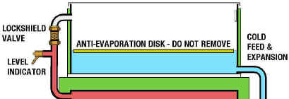 The Feed and Expansion Tank is fitted with a low absorption polystyrene disk, that floats on the surface of the water, preventing evaporation. It is important that this is not removed as increased evaporation will result in more frequent top-ups. The Feed and Expansion Tank is fitted with a low absorption polystyrene disk, that floats on the surface of the water, preventing evaporation. It is important that this is not removed as increased evaporation will result in more frequent top-ups.The Vent Pipe is fitted with a lock-shield valve, and a level indicator (drain cock). The lock-shield valve has a drilled hole to allow air to vent when the valve is shut, but will prevent surges of hot water into the F&E Tank. During filling the lock-shield valve is to be opened to allow air to vent quickly. Also during filling, the level indicator should be used to set the correct water level in the F&E Tank. It is important that excess water is drained off, as overspill may occur when the unit first heats up and the water expands. |
| 2 GENERAL REQUIREMENTS |
| 2.1 |
| 2.2 |
| 2.3 |
| 2.3.1 |
| 2.3.2 |
| 2.4 |
| 2.5 |
| 2.6 |
| 2.7 |
| 2.8 |
| 2.9 |
| 2.10 |
| 2.11 |
| 2.12 |
| 2.13 |
| 2.13.1 |
| 2.13.1.1 |
| 2.13.1.2 |
| 2.13.1.3 |
| 2.13.1.4 |
| 2.13.1.5 |
| 2.13.1.6 |
| 3 COLD MAINS SUPPLY. |
| 3.1 |
| 3.2 |
| 3.3 |
| 3.4 |
| 3.5 |
| 4 CONNECTIONS TO Heat Bank Thermal Store. |
| 4.1 |
| 4.2 |
| 5 WIRING |
| 5.1 |
| 5.2
|
| 5.3 |
5.3.1  The
Horstmann Electronic 7 The
Horstmann Electronic 7 Immersion Heater Controller
controls the times
when water is heated. When set to timed, the unit will heat up on
overnight electricity. To heat the cylinder up at other times, a boost
facility is provided. Immersion Heater Controller
controls the times
when water is heated. When set to timed, the unit will heat up on
overnight electricity. To heat the cylinder up at other times, a boost
facility is provided.
The Electronic 7 should be wired to the Consumer Units as shown in the schematic opposite. |
| 5.3.2 |
| 5.3.2.1 |
| 5.3.2.2 |
| 5.3.2.3 |
| 5.3.2.4 |
| 5.3.2.5 |
| 5.3.2.6 |
| 5.3.2.7 |
| 5.3.2.8 |
| 6 FILLING. |
| 6.1 |
6.2 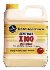 It is important that SENTINEL X100 Inhibitor is used to protect the Heat Bank Thermal Store. It is important that SENTINEL X100 Inhibitor is used to protect the Heat Bank Thermal Store. Use 1 litre per 100 litres of stored water. Label the unit as protected with the label provided. Contact Betz Dearborn direct for method statements on 0151 424 5351 Alternatively contact Fernox on 01799 550811. |
| 6.3 |
| 6.4 |
6.4.1  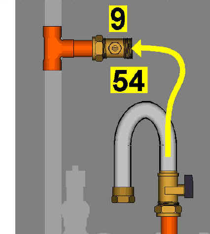 |
| 6.4.2 |
| 7 COMMISSIONING. |
| 7.1 |
| 7.2 |
| 7.3 |
| 7.4 |
| 7.4.1 |
| 7.4.2 |
7.4.3
 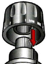 The Valve is adjustable from 27°C to 67°C, and has a lockable head, as shown. Typically the valve should be set to obtain a supply temperature of 65°C, to protect against Legionella. Check the setting of the Thermostatic Blending Valve by opening a hot water outlet to a low flow rate (approximately 10 litres per minute) and measuring the output temperature. The head of the Blending Valve may be locked in position if required. The Valve is adjustable from 27°C to 67°C, and has a lockable head, as shown. Typically the valve should be set to obtain a supply temperature of 65°C, to protect against Legionella. Check the setting of the Thermostatic Blending Valve by opening a hot water outlet to a low flow rate (approximately 10 litres per minute) and measuring the output temperature. The head of the Blending Valve may be locked in position if required.The graph shows the pressure drop across the valve for various hot water flow rates. |
| 7.5 |
| 7.6 |
| 8 FAULT FINDING. |
| 8.1 |
| 8.2 |
| 8.2.1 |
| 8.2.2 |
| 8.2.3 |
| 8.2.4 IMPORTANT: The unit should be protected with scale / corrosion inhibitor to protect the pump. A build up of material within the pump suggests that inhibitor has not been used, and the system will probably need flushing. |
| 8.2.5 |
| 8.2.5.1 |
| 8.2.5.2 |
| 8.2.5.3 |
| 8.2.6 |
| 8.2.7 |
| 8.2.8 |
| 8.2.9 |
| 8.2.10 |
| 8.2.11 |
| 8.3 |
| 8.3.1 |
| 9 Servicing |
| 9.1 |
| 9.2 |
| 9.3 |
| 9.3.1 |
| 9.3.2 |
| 9.3.3 |
| 9.3.4 |
| 9.3.5 |
| 9.3.6 |
| 9.3.6.1 |
| 9.3.6.2 |
| 9.3.6.3 |
| 9.3.7 |
| 9.3.8 |
| 9.3.9 |
| 9.3.10 |
| 10 Spares |
|
|
| 11 Users Instructions |
| The Heat Bank Thermal Store Unit should be set up by the installer according to the instructions given in the Installation and Commissioning Instructions. |
|
| Please not that under certain circumstances, increasing the flow rate of water from a tap or shower may result in the water temperature dropping. Likewise, reducing the flow rate will result in the temperature increasing - the temperature will not increase above the setting of the Thermostatic Blending Valve. |
| The Horstmann Electronic 7 Immersion Heater Controller
controls the times
when water is heated. When set to timed, the unit will heat up on
overnight electricity. To heat the cylinder up at other times, a boost
facility is provided. For copies of Instructions, please telephone Horstmann on 01225 421141. |
| Your Heat Bank Thermal Store Unit may occasionally need topping up with water. The wiring centre on the front of the unit is fitted with a red neon which, when lit, indicates that topping up is required. Please refer to Section 6 - Filling, in the Installation Instructions for further details. |
|

 The unit is fitted with a Mixcall III Thermostatic Blending Valve, to control the hot water temperature, and prevent scalding.